

06 Audi A4 2.0t Ac Compressor Wiring Diagram Free Updated
06 Audi A4 2.0t Ac Compressor Wiring Diagram Free Updated
Fuse box diagram Audi A4 (B7)
For the Audi A4 B7 (8E, 8H) 2004, 2005, 2006, 2007, 2008, 2009 model year.
Cigarette lighter fuse – (fuse box in passenger compartment, fuse №33/15A)
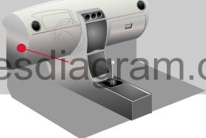
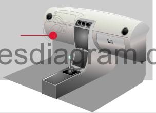
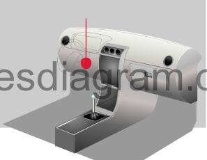
Fuse box in rider compartment.
fuse box location.
fuse box diagram.
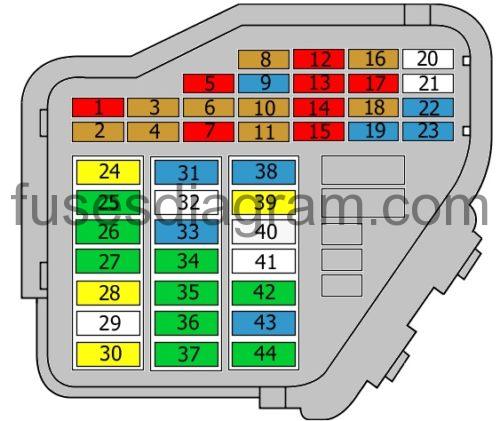
legend.
| Fuse | Amps | Circuits protected |
|---|---|---|
| 1 | 10A | Air-conditioning control unit Climatronic |
| ii | 5A | Footwell lite(s) |
| 3 | 5A | Heated washer jets |
| iv | 5A | Cooling fan control unit |
| 5 | 10A | Rear roller blind Multifunction switch Oil level sensor Oil temperature sensor Navigation arrangement Parking aid command unit |
| 6 | 5A | Air quality sensor Climatronic Heated front seat(s) Air-conditioning high-pressure sensor TCS/ESP push |
| 7 | 10A | Traction command switch Clutch switch ABS command unit Brake pedal switch |
| 8 | 5A | Telephone Telephone amplifier |
| 9 | 15A | Restriction servo relay |
| 10 | 5A | Headlight range control |
| 11 | 5A | Airbag control unit Airbag warning low-cal |
| 12 | 10A | Diagnostic connector |
| xiii | 10A | Control unit, steering column electronics |
| 14 | 10A | Restriction light switch |
| 15 | 10A | Control unit with display in the nuance panel insert Navigation system CD actor |
| xvi | 5A | Garage door opener |
| 17 | 10A | Pelting sensor Daylight running system Parking assistance control unit of measurement |
| 18 | 5A | |
| 19 | 15A | Fog light(due south) |
| 20 | Not used | |
| 21 | Non used | |
| 22 | 15A | Door control unit of measurement, front left Door control unit, front right |
| 23 | 15A | Door command unit, rear left Door command unit, rear right |
| 24 | 20A | Condolement system electrics |
| 25 | 30A | Blower Ac |
| 26 | 30A | Heated rear windscreen |
| 27 | 30A | Trailer detection control unit |
| 28 | 20A | Fuel pump |
| 29 | Not used | |
| 30 | 20A | Sliding roof control unit of measurement |
| 31 | 15A | Reversing light switch Mass airflow meter Automatic transmission command unit of measurement Light sensor Starter relay Selector handle lock solenoid Diagnostic connector Automatic anti-dazzle rear-view mirror |
| 32 | Non used | |
| 33 | 15A | Cigarette lighter |
| 34 | 30A | 12V socket |
| 35 | 30A | Accessory socket |
| 36 | 30A | Power supply command unit Rear wiper motor |
| 37 | 30A | Power supply control unit Headlight washer pump |
| 38 | 15A | Alarm horn Comfort organisation electrics Interior monitoring |
| 39 | 20A | Radio Audio amplifier |
| xl | 25A | Horn |
| 41 | Additional heater control unit Remote control receiver | |
| 42 | 30A | ABS control unit |
| 43 | 15A | Mass airflow meter Engine direction EGR Main relay Engine control unit of measurement Engine control unit relay |
| 44 | 30A | Climate control unit of measurement |
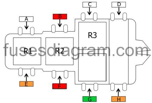
Fuse and relay box №1.

fuse box diagram.
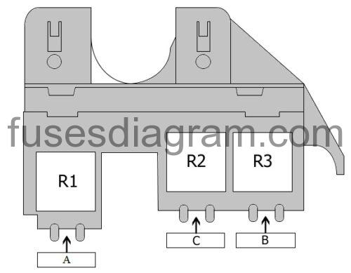
legend.
| Fuse | Amps | Circuits protected |
|---|---|---|
| A | Not used | |
| B | 40A | Boosted heater |
| C | 60A | Boosted heater |
| R1 | Special vehicles | |
| R2 | Low-output heating relay | |
| R3 | High-output heating relay |
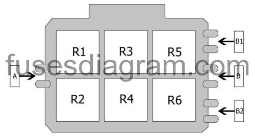
Fuse and relay box №2 in passenger compartment.
fuse box diagram.
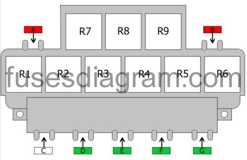
fable.
| Fuse | Amps | Circuits protected |
|---|---|---|
| A | 10A | Rear roller blind |
| B1 | 10A | 12V socket |
| B2 | 10A | Rear roller blind |
| C | not used | |
| D | 30A | Window regulator |
| E1 | 30A | Driver'south seat adjustment |
| E2 | 10A | Driver'due south seat aligning |
| F | 30A | Window regulator |
| Yard | 30A | Trailer towing module |
| R1 | Fuel pump relay Additional relay, fuel pump | |
| R2 | Servotronic control unit | |
| R3 | Starter motor relay | |
| R4 | Starter motor relay Brake servo relay | |
| R5 | Heated rear windscreen relay | |
| R6 | Ten contact relief relay | |
| R7 | Not used | |
| R8 | Horn relay | |
| R9 | Not used |
Fuse and relay box №3 in passenger compartment.
fuse box diagram.
legend.
| Fuse | Amps | Circuits protected |
|---|---|---|
| A | Non used | |
| B | 10A | Vermin repellent organisation |
| C | Not used | |
| D | Not used | |
| Due east | 40A | Special vehicles |
| F1 | 10A | Special vehicles |
| F2 | 40A | Cooling fan (60A also used) |
| Chiliad | 30A | Cooling fan (40A and 60A also used) |
| H | 40A | ABS control unit |
| R1 | Not used | |
| R2 | Not used | |
| R3 | Special vehicles | |
| R4A | Special vehicles | |
| R4B | Taxi package |
Relay box in passenger compartment.
relay box diagram.
legend.
| Fuse | Amps | Circuits protected |
|---|---|---|
| A | Not used | |
| B | Not used | |
| B1 | Not used | |
| B2 | Not used | |
| R1 | Alarm system Chief beam Or Chief axle relay | |
| R2 | Special vehicles Or Taxi package | |
| R3 | Alarm organisation control unit of measurement Or Siren relay | |
| R4 | Alarm arrangement control unit Or Siren relay | |
| R5 | Alarm relay Right direction indicator Or Flasher relay | |
| R6 | Alert relay Left direction indicator Or Not used |
Fuse box №2 in passenger compartment.
fuse box diagram.
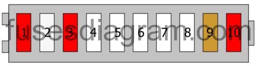
legend.
| Fuse | Amps | Circuits protected |
|---|---|---|
| ane | 10A | Special vehicles Or Taxi package |
| 2 | 25A | Special vehicles Or Alarm system |
| three | 10A | Special vehicles Or Taxi package |
| iv | Special vehicles | |
| five | Special vehicles | |
| 6 | Special vehicles | |
| 7 | Special vehicles | |
| eight | Special vehicles | |
| 9 | 5A | Special vehicles Or Radio |
| ten | 10A | Special vehicles Or 12V socket |
Fuse box in engine compartment Audi A4 (B7).
fuse box location.
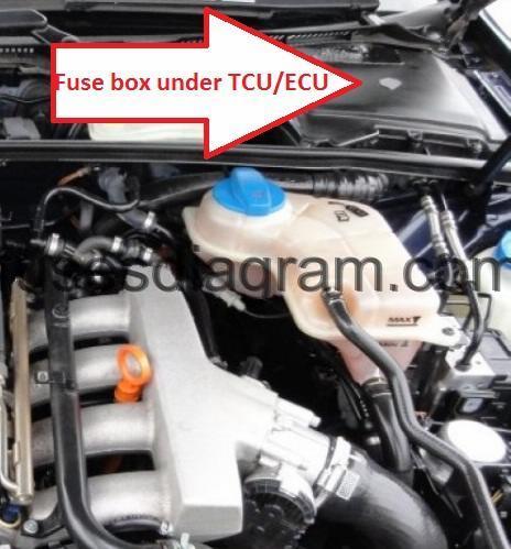
fuse box diagram.
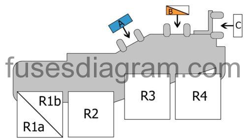
legend.
| Fuse | Amps | Circuits protected |
|---|---|---|
| A | 15A | Engine electronics |
| B1 | Not used | |
| B2 | 40A | Secondary air injection pump |
| C | Not used | |
| D | 20A | Engine control unit |
| E | 15A | Injectors |
| F | Non used | |
| G | 15A | Engine electronics |
| R1a | Not used | |
| R1b | Not used | |
| R2 | Principal relay | |
| R3 | Secondary air pump relay | |
| R4 | Not used |
DOWNLOAD HERE
06 Audi A4 2.0t Ac Compressor Wiring Diagram Free Updated
Posted by: velacubled.blogspot.com
0 Response to "06 Audi A4 2.0t Ac Compressor Wiring Diagram Free Updated"
Post a Comment